|
Building Bitts...The New Life of a Tugboat!We have several Little Bitts members who are currently "under construction". These guys have graciously chosen to share their photos, their ideas, their mistakes (Yes! These are men who admit their mistakes and will show you how to fix them!), and their progress! Bob Cosler is building a Candu E-Z. He lives in Pennsylvania, about an hour north of Philadelphia. His tug will be called "Electra", with a story attached! He says: "Yes I have a name. As you may or may not know I have decided to use the electric golf cart motor method of propulsion laid out in the plans. Because I intend for my grandchildren to use the tug I thought this no muss, no fuss method of propulsion to be the best choice. Ironically, my mother’s given name was Electra (believe it or not her brother’s name is Electro). Therefore, what better name than Electra in honor of my dear departed mother. Besides, it’s a lot better name for a mini-tug than her nickname (by which everyone knew her) Dolly! Truth is stranger than fiction." Bob purchased his plans in 2004, spent some time thinking about it, and took the plunge. Both of these guys have a great sense of humor, and it has been a lot of fun working with them, sharing their "moments"! I will try to keep these broken into their own group, first Bob's EZ and then Danny's 10! That way we won't confuse anyone. Read through all of it though, as both have some great tips and ideas no matter WHICH boat you are building!
Dennis Banta is building a Candu E-Z. He lives in Albany, Oregon…about 65 miles south of Portland. He is sharing his photos with us! Dennis is planning on naming her "Fiddle dee dee." "That was a favorite saying from my grandmother & it will be in memory of her...Edna Banta". His wife Jeanette has been so supportive of this project that the name may end up "Lady J", also! Either one is a great choice! Ron Carter of Branch, Michigan is building the Mary C. He calls it a "Perfect 13"! Branch, MI is a rural area in western Michigan about 20 miles east of Ludington.
William Powers of El Cerrito, Ca is busy building "Gigi", his Micro 9 and has shared some of his photos with us! We have several more builders who have sent us photos! Thanks everyone for sharing! We all enjoy seeing the finished product!
Bob Cosler's Candu E-Z, "Electra", Trials and Tribulations!
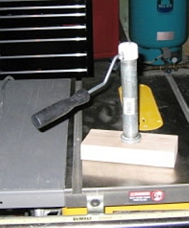
Bob Cosler has "invented" a roller cleaner, shown above. In his words: "I am showing a device that I made yesterday to remove cured epoxy from the rollers that I am using to remove air bubbles from the epoxy resin/cloth. The 4” roller is shown in front of the soaking container. I was concerned about VOC (volatile organic compounds) emissions using acetone to clean this roller and a similar 6” wide model. I didn’t want to use an open container and allow the acetone to evaporate into the air. So I purchased an 8” pipe nipple which is 1” in diameter. In addition I purchased two end caps, (one steel, the other PVC). I used a 1 3/4” hole saw to drill about 2/3 of the way thru a 2X4 scrap about 10” long. After chiseling out the plug from the hole I attached the steel cap to the nipple (be sure to use pipe dope or Teflon tape to allow tightening the cap very tight), place the nipple (cap down) in the hole; and using a piece of scrap wood to protect the other end and threads, I drove the cap into the 2X4. This creates a stand for the soaking chamber. I chose a drill the size of the roller frame rod and drilled a hole in the side of the PVC cap about ¾ of the way to the top of the cap (see picture). Then using a hack saw I cut a slot in the cap to the hole just drilled. This creates a slot for the roller frame rod. Fill the nipple about 2/3 full and place your roller in it over night and in the morning the epoxy peels off like skin. Poor the acetone into a glass jar or airtight can and reuse it the next time. I’m having a blast (or is it the acetone fumes?)!
Bob"
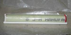
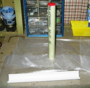
Bob also has made his own rudder tube and the mold for it. In his own words "The pictures above are the rudder tube in the “mold” that I fashioned from a piece of 2” PVC pipe (Yes, the very same pipe from which the propeller tube is made). I sawed the 2” pipe in half lengthwise and it turns out that it is just the right diameter for the rudder tube to cure in and cure very smoothly I might add. I used 6.5 oz fiberglass cloth that is 13” long and 38” wide. The 38” width of the cloth when wrapped around the 1” PVC pipe makes the tube almost a perfect 1½” diameter when soaked with resin. If you laid the tube on a flat surface to cure, it would of course be flat on one side. This “mold” prevents that from happening. Note the red modeling clay in the ends of the rudder tube to prevent intrusion of resin into the inside of the tube. That’s my super mold release film (waxed paper) on the workbench and in the mold."
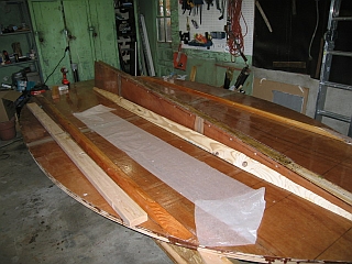
This is the bottom of the hull of Bob's "Electra". You can see the fiberglass cloth that he has been working with. "This picture shows the boat bottom in its current state with the keel added with two aft fairing strips. The forward fairing strips are only positioned, not screwed and glued. Everything but the side keels and the fairing strips has two layers of cloth and epoxy resin."
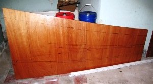
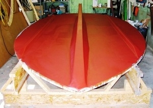
This is the starboard section of the "Electra"...."This picture shows the outside of the starboard pieces with a good seam in the middle and all the lines lining up. In the background you can see the 5 gallon containers of epoxy resin (2 of 6) with which I am putting this little darling together. I have coated all of the side pieces (those shown plus the several aft pieces) with a thinned epoxy as a sealer and my next job is to apply cloth to those pieces." Bob has instructions that will help you in your building process:Glassing the Bottom of the Candu EZ® These notes are intended as a supplement, not a replacement of, the instructions for assembly provided in the plans for the Candu EZ®. Applying fiberglass cloth and epoxy resin over the marine plywood bottom surface of the Candu-EZ is no small challenge, at least for a novice. In general fiberglass composite construction, of the type attempted here. is pretty forgiving. Mistakes such as runs or drips, voids or wrinkles and even mixing misadventures are relatively easy to correct. Unfortunately, this can lead to overconfidence or even sloppiness in the approach to this activity. Sloppiness in application of the resin will undermine the project in so many ways that the amount of work needed to complete the project increases exponentially. Do whatever is necessary to make and keep the work area neat and clean. It will pay multiple dividends. In general the following remarks apply to the application of epoxy resin and fiberglass cloth. Although I suspect they apply to other resin and reinforcement systems. Acknowledgement of these characteristics will improve the outcome of the project and reduce the work dramatically.1. Prepare thoroughly a. Have all supplies, ready BEFORE you start to mix. Buckets, stir sticks, protective gloves, thickener, thinner, paint mixer for larger batches, lots of towels and rags.b. Write down the amounts of resin and hardener that you will be using. I have done almost all mixing by weight rather than volume because it is easier to read a scale as you are adding to the container than to have to hold the container at eye level as you pour. Some sources recommend weighing the cloth and then mixing an amount of resin that is equal to the weight of the cloth. I found this too stingy and often used 1½ to 2 times the weight of the cloth for the amount of resin to mix – better too much than too little.c. Clean, sand, and re-clean (note the order) the surface to be covered. 2. Rough to start, rough to finish - Imperfections in the surface will not be corrected by rolling, pouring or brushing on liquid resin. Although the resin generally flows out quite well, it will leave imperfections as raised or depressed areas just as they were prior to application of the resin. Therefore, correct depressed imperfections first with thickened resin (preferably using a thickener that will cause the resin to gel if undisturbed such as fumed silica). If there are raised imperfections in the plywood, remove them by sanding. Once resin has been applied depressions that occur must be again filled, but raised areas in cloth or resin should be removed with a chisel or scraper rather than sanding them off. Trying to sand off drips or raised areas will generally result in the removal of significant amounts or resin or even cloth from around the raised area. Fixing these issues as soon as the resin has set up and is no longer sticky to the touch is generally easier than waiting until the resin has reached its full hardness. I have provided the schematic of the bottom so that reference points can be identified. All four panels making up the bottom and the parts of the center and side keels were primed with epoxy resin prior to assembly. However, it is my experience that obtaining a chemical bond with this prime coat provides the greatest insurance against future problems. So, think out the assembly time, it will take longer than you think. And plan the priming so that you can add additional coats or resin, or resin and fabric, while the previous coat is still curing (24-36 hours depending upon temperature). Notes to the diagram1. Use a scarf joint for the top side of middle (longitudinal) seam (1). Your belt sander with 50 grit paper will make quick work of creating the bevel for these joints. Use the glue lines of the plywood layers as reference lines to obtain an even taper of about three inches of each edge (total width of joint 6”). Do this sanding prior to joining any panels and it will be much easier. WAIT!! Don’t create a scarf on the aft 2’ of the topside of the bottom as this is where the aft doubler will be placed. WAIT AGAIN!! Don’t scarf the area where the cabin bulkhead crosses amidships. These surfaces should be flat to obtain a good bond when they are “glued” in place. The bottom side of the middle seam will be joined by the keelson. Choose the very straightest of 2X4s to make this piece. If this piece is even slightly bowed or racked (twisted), it will create havoc when you try to get the bottom level. More about the bottom later. Attaching the sides I joined the three pieces of the sides together with scarf joints on the outside and battens on the inside prior to attaching them. I also added two layers of 6 oz cloth to the outside and one layer of 6 oz cloth to the inside prior to attachment. I make every attempt to apply resin when pieces are in a horizontal orientation so that the resin flows out evenly with out runs. I also added the deck stringer on the starboard side prior to attachment of the side, CONTRARY TO Berk’s suggestion. More about that little adventure in a bit. Since you can, with a bit of ingenuity, clamp a side in place I strongly urge a test fit of both sides individually. To facilitate this, I added a clamping block to both of the bulkhead jigs. Use the lines that you have drawn on the sides to aid the fitment, especially the lines defining the edges of the aft cabin wall witch coincide with the placement of the bulkhead jigs. Also extend the lines for the water line and deck stringer onto the stem so that you have reference points to align the sides during attachment. I didn’t do this initially and as a result have about a 1/8 inch difference in the sides which will have to be shimmed or corrected in some way. Good news is that when I laid a straight-edge across the top of the sides amidships the top of the sides were dead-on level. Having joined the side pieces together, it was a bit of a challenge for me to single handedly attached the sides to the stem and bottom. Nonetheless, the port side went on reasonably well by clamping the side to the bulkhead, then bending the side along the bottom to the stem and checking the fit. Adjust as needed then put the first screw at the top of the side where it joins the stem (approximately 1” from the top). Readjust as needed, check stem for plumb and add several more screws or nails to the stem/side joint. Then proceed around the bottom, checking all the will for fit, plumb and alignment. Now about that deck stringer - My thought was that adding the stringer prior to attachment of the side would allow me to add the second layer of glass while the side was horizontal; and thus covering any holes made during the stringer install. This was true and I was gloating to myself (always a bad idea) while I tested the strength of the install and noted how stiff the side now was. Well! Just wait till you try to install that side to the stem and bottom! I haven’t had that much fun since my last root canal. The side is installed, but not without help; and not without some stripped screws that had to be drilled out, sawed off, and replaced. Needless to say, it wasn’t worth the ease of applying the cloth and resin. Perhaps installing only one layer of the stringer prior to hanging the side might work. So winter is closing in on northeastern Pennsylvania and the days of moderate temperature are all but gone. This means that work on the tug will have to be transferred to the basement where I have begun assembly of the rudder and will be glassing the deck and shelf for install at the first sign of a reasonably warm day. We’ve all got lots to be thankful for, so have a HAPPY THANKSGIVING, 2008! 8/10/08 Attached is a picture of the bottom with four coats of glass, five coats of Interprotect 2000E primer, and 1 coat of Interlux Micron CSC (2 more coats to go). The painting should be finished at the end of this week and then the bottom will be “muscled over”. Attachment of the sides can then begin. I fussed along time (probably too long) trying to get the bottom very smooth, only to realize that the primer and the bottom paint, will with cover the rough spots or undo the smoothness to the point that most of the sanding didn’t matter. I will follow with some notes about my experiences with glassing the bottom.
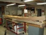
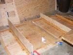
Additional "HINTS" From Bob!1. I suspended a lot of parts from the ceiling in my garage because I had an issue with having to move the cut parts around. I used a piece of particle board and ropes at the corners with screw eyes in the ceiling. I had the chine logs, rub rails, shelf pieces, forward deck and some other misc pieces suspended in this way and it saved me a bunch of time trying to deal with parts that don't stand up well on there own. 2. I noted the saw horses in the picture on Dan Boucher's page, and while I started out cutting out the bottom and other pieces on saw horses, it does become necessary to establish a level platform on which to build the hull. I scrounged two, 3"X10" manufactured floor joists 18' long off of a local lumber yards junk pile. I wish that I could tell you that they were free but alas good ole American entrepreneurship prevailed and I paid $60 for both. Not bad when you consider these for somewhere around $10.00 per foot. 3. I lucked into a fairing stick as well. I replaced some exterior trim around my house with a product called AZEK. It is an extruded polystyrene product. Very dense and heavy for its size. It comes in long (sort of unmanageable) lengths of 18 or 20 feet I believe. I had ripped a piece about 3/4" wide off one of the long sections of flat trim that is also about 3/4" thick. This made an excellent fairing stick. It bends uniformly throughout its length (as opposed to wood which may be affected by the grain or knots). Another thought is using the pieces that get ripped off the sides of the base of the keel, since these are about 10' long."
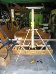
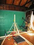
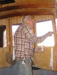
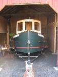
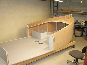
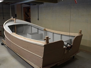
9/4/08 (Re: ABOVE 2 PHOTOS) Susie:Attached is a picture of “Electra” right side up., Yep, it finally happened, I got tired of looking at the bottom and decided it was time to turn her over. Having done so, the next item on the building sequence list was the installation of the stem. In the plans it sounds as though this is a simple process, just get it straight or the whole boat is crooked. Whew!! No pressure! So …. What you see is my response. Just a few notes that you might want to include on the web page. Follow the directions with regard to preparing the stem, install the nailing strips, round the corners and drill the holes for the bow eye. Drilling the holes for the bow eye is much more accurate and easier if you have access to a drill press as I did. Because I knew that some sort of bracing must be used I decided to use one of the holes for the bow eye to insert a 6 inch bolt to which I attached a piece of punched steel. This steel piece, which could have just as easily been wooden, was attached at each end to wooden pieces that are the same dimension as those suggested to be made for the deck and shelf supports (I had them left over from making the support). Note that these are clamped to a 2X2 which is clamped to the bottom in line with the back of the stem. To provide fore and aft support I used a piece of scrap 2X4 through which I drilled a hole to accept the bolt that passes through the stem. The other end is screwed to a 2X4 that is also clamped to the bottom. Clamping in all these places offers the advantages of not drilling holes in the bottom (which although I am told I will have to do eventually, I am steadfastly resisting). And, the clamps provide an easy method of quickly attaching the apparatus after you have mixed and applied the epoxy resin to the stem and bottom. In the one picture you can see a yellow plastic post level attached to the stem that made the whole process more accurate and easier. I also ran a string line over the top of the stem along the center line of the boat and the stem, just like Berk told us to do.That’s it, more to come.
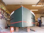
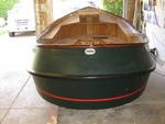
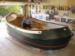
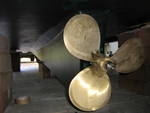
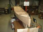
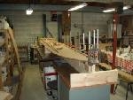
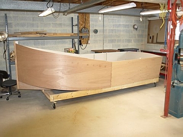
Dennis Banta's "Fiddle Dee Dee"The next builder is Dennis Banta. Here are 4 photos of his hull and prop. Beautiful work, Dennis!! 2/20/09 "I believe I’ve already mentioned this, but I’ll do it again just in case I didn’t. I lengthened the boat 30 inches and added twelve inches to the cabin length. The cabin bulk head is nine feet from the stem. The overall length of the tug is sixteen and a half feet. I increased the beam of a couple of inches. These changes allowed for two “V berths” forward, a small galley & head. Also, the area aft of the bulkhead is six inches longer. I’m pleased with the lines of the boat, as you can see by the photo’s that I sent a couple of weeks ago, that are on your site. The boat is electric powered, per specks. The tug went together per plans with no problems. It did drink up 27 gallons of Systems Three epoxy and a pile of plywood!The plans are great & everything was perfect. I’m getting excited to have it ready to put in the water for Depoe Bay’s Wooden Boat Festival mid April, here in Oregon. I plan on putting it in the Wooden Boat Festival in Toledo, Oregon late August also. I was going to put it in Port Townsend, WA. Wooden Boat Festival in Sept., but decided to wait until next year.I am still up in the air on the name…I originally sent you the name of “Fiddle De D,” but am strongly leaning towards the name “Lady J” for my wife (her name is Jeanette), because she has been so supportive through out this whole project.Best regards, Dennis BantaAlbany, OR"
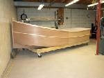
Here are more photos that Dennis Banta has sent of his progress!
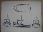
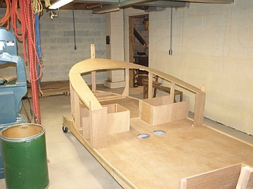
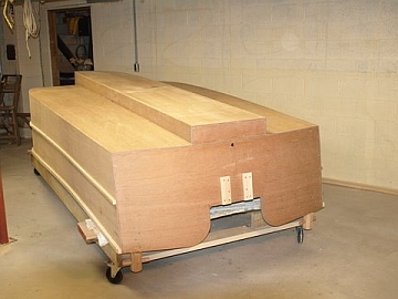
Ron Carter's Mary C, A Perfect 13A couple of pictures of the Mary C. I call it a Perfect 13. I tookthe lines from the Candu Jr. to the back of the house. Extended thehouse by 1 foot and then took the transom from the Perfect 10 andplaced it to give a 13' overall length. being the contrarian that Iam I'm building in the "screw and glue" method so there is a lot ofstructural layout that has to be worked out. I've never developed ameaningful relationship with epoxy and glass. Have all of the panelsfor the hull bottom cut and well on the way to assembled. The CanduJr. layout is the largest of Berkeley's designs that will come out ofmy basement shop. Great to have a well heated and lit shop in theMichigan winter. Will post as progress is made.Ron Carter A couple more pictures as I move along. Won't make a lot of progressnow until after the holidays. For those who are interested theplywood is Meranti BS1088, the framing is white oak. Stainless screwsand PL Premium adhesive in the joints. No glass or resin will beharmed int the building of this boat. Personal chioce on my part.Ron
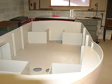
"The 4 pictures show the sequence from the bottom, stem, and transom toplanked sides. I have not yet made the final cut on the sheer line toshape the top of the hull. Sincce I was flying blind with only asketch for plans I cut the sides extra high and will spring a battento the sheer shape and cut them accordingly. House is next. If thereis any interest in further discussion I'd be happy to have you sharemy contact information with anyone interested.Ron 2/7/09"
"Might as well have the latest photo. Hull is essentially finishedexcept for the transom cut for the engine. Just bought a 15 Johnsonfor power. Next photos will show the construction of the wheel house.2/13/09"
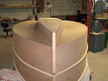
"2/26/09The upright picture is just before we turned her over. The other 2show some detail of the bottom. Will finish the outside of the hulluo to the gunwales comletely before turning her back over for thepilot house"
Dan Hewitt's Annabelle
Good Afternoon, I thought I would forward along a couple of pictures of my Micro 9 I built. It took me 3 months working nights and weekends. The plans were easy to follow and I learned a lot about fiberglass and plywood along the way. I'm looking forward to my next build.
Enjoy
Dan Hewitt
Bob Erickson Shares His 10'
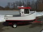
I received plans from Berkeley Engineering and began construction of my perfect 10 mini tug in the fall of 2008. I love to work with wood, but had no experience using fiberglass. Sectioning off a 10X24 area in my garage, insulating, and heater installed, I worked every spare hour through the winter. Located on Little McDomald lake by Perham, Mn., I envy those with warmer working areas, and that have open water year around.
By May, 2009, construction nearly complete, I set a launch date for July, 4th.
I installed two chain hoists at each end of the small work area to lift & roll the boat, making sanding, fiberglassing, and painting easier.
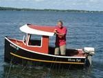
Launch day arrived 2 weeks early. No leaks, and it handled and operated perfect. The proudest boat on the lake.
A surprise came when my son, a woodworker, living in Stresa, Italy, arrived with a beautiful ships wheel. Hand made from a large block of wood from an old olive tree.
"Olive Oyl", is powered by a 15 hp Johnson
Thanks, Bob Erickson, Fargo, N.D.
William Powers Shares His Building Process of "Gigi"Well work progresses steadily here in the East Bay. I have shaped the hull bottom and am adding the bulkheads. The transom is all set and im rapidly approaching the costly (fiberglass everything) stage. Just a few pics from the assebly plant LOL. Id also like to thank all the guys at Tap Plastics here in El Cerrito for all their help and advice !!! Bill Powers
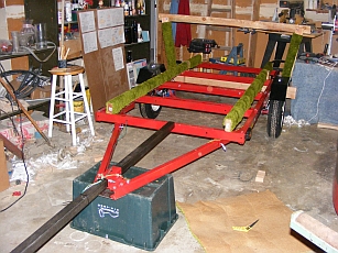
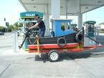
2/20/09"Bill Powers Trailer--Well wHile cleaning out the attic this last weekend my Dad and I found just enough 1970's left over Lime green shag carpeting to cover my trailer and booyahh I got the wiring right on the second try !!! The cabins starting to go up slowly but its been wet and cold a lot so Ive been not glassing as fast as I was. Hopeing to get her in the water by April 1 ( no really ) Ive been vetoed on naming her Das Boot so I,m considering Gigi ( my late grandmother's nick name ) since its been completely constructed in her garage. That trailer is a beauty, Dennis! Ha!
William Powers....More!
Well it's been a while. I haven't seen my completed pics up so I thought I would send you a few more. Happy holidays to all of you and yours!!!(Sorry, I am very late posting this!) Hoping to put gi-gi up for sale this spring and get started on a 14 footer >:) Yeah I'm addicted :)
John's Toot Uncommon
Hi Susie,
Thought you and your viewers might like to see a project I completed this spring and enjoyed throughout the summer with my grandchildren. Captain Grandad had to get himself a uniform and a whistle. I called her TOOT UNCOMMON. Passengers are also given a Toot-sie Roll to enjoy while speeding down the lake with the small electric motor. Boat length is 8 feet. Take care - John (Toot Toot)
|